Hardware Configuration
Launching Hardware Configuration Panel
An “Open Hardware Config” named button is available on the main menu of GUI application of BEST Toolbox. Clicking it would lead you towards the Hardware Configuration area comprising of following view:
Adding Output Devices (Host PC Controlled)
You can allow BEST Toolbox to use your host PC to control the stimulation devices (output devices). Use the following pairs of parameters in order to allow so:
- Device Type: Select Output Device from drop down menu
- Select Device: Select your device manufacturer from the given list of devices
- Device Reference Name: Give any meaningful reference name to your device
- COM Port Address: Connect the stimulation device to your Host PC using a serial COM cable and give the address of COM port here e.g. ‘COM1’
- Add Button: Click on the add button at the bottom and the device will be shown on the left list box
The overall populated panel in this case would look like as shown in figure below. 
Adding Output Devices (bossdevice Controlled)
You can allow BEST Toolbox to use your bossdevice to control the stimulation devices (output devices). Use the following pairs of parameters in order to allow so:
- Device Type: Select Output Device from drop down menu
- Select Device: Select your device manufacturer from the given list of devices
- Device Reference Name: Give any meaningful reference name to your device
- COM Port Address: Connect the stimulation device to your Host PC using a serial COM cable and give the address of COM port here e.g. ‘COM1’ BOSS Box Output Port: Port number that is connecting the Boss Box trigger output to your stimulation device trigger input e.g. 1 BOSS Box Input Port: Port number that is connecting the Boss Box trigger input to your stimulation device trigger output e.g. 1
- Add Button: Click on the add button at the bottom and the device will be shown on the left list box
The overall populated panel in this case would look like as shown in figure below. 
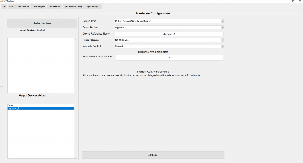
Adding Output Devices (Digitimer)
You can allow BEST Toolbox to control Digitimer using Arduino or Manually using Keyboard responses. Use the following pairs of parameters in order to allow so:
- Device Type: Select Output Device from drop down menu
- Select Device: Select your device manufacturer from the given list of devices, in this case Digitimer
- Device Reference Name: Give any meaningful reference name to your device
- Trigger Control: Select from the given options of , bossdevice, Host PC Serial PCI Card, Host PC Parallel PCI Card, Arduino, Raspberry Pi, Manual and fill the subsequent relevant fields
- Intensity Control: Select from the given options of, Arduino or Manual and fill the relevant subsequent relevant fields
- Add Button: Click on the add button at the bottom and the device will be shown on the left list box
The overall populated panel in this case would look like as shown in figure below.
Adding Input Devices (BOSS Box Controlled)
You can allow BEST Toolbox to use your BOSS Box to take input from the recording system (input devices). Use the following pairs of parameters in order to allow so:
- Device Type: Select Input Device from drop down menu
- Select Device: Select your device manufacturer from the given list of devices or FieldTrip buffer
- Device Reference Name: Give any meaningful reference name to your device
- Protocol File Name: Give the name of Protocol file available in MATLAB’s current directory. This file is used to extract the channel names being streamed from your recording device.
- Add Button: Click on the add button at the bottom and the device will be shown on the left list box
The overall populated panel in this case would look like as shown in figure below. 
Adding Input Devices (FieldTrip Buffer Controlled)
You can allow BEST Toolbox to use your FieldTrip real-time Buffer to take input from the recording system (input devices). Use the following pairs of parameters in order to allow so:
- Device Type: Select Input Device from drop down menu
- Select Device: Select your device manufacturer from the given list of devices or FieldTrip buffer
- Device Reference Name: Give any meaningful reference name to your device
- Hose Name: Type the Host name or IP address in use. e.g. localhost
- Port Address: The port address used to stream the real-time buffer. e.g. 2222
- Channel Labels: The channel labels can be typed in as a row vector e.g. 1:16 or {‘A’,’B’,’C’} or {‘C3′,’FCz’} etc
- Block Size: Block size of a Field trip buffer e.g. 500 samples
- Sampling Rate: Sampling rate in hertz e.g. 1000 Hz
- Add Button: Click on the add button at the bottom and the device will be shown on the left list box
The overall populated panel in this case would look like as shown in figure below. 